Timer And Contactor R Relay Diagram - 1. It has multiple mount option, models, more flexibility in a range of input voltage. Each relay activation will cause the light to toggle. Special function flasher timing relay. 3 pole contactor without base contact 4 pole contactor with 4 n.o. Off on time delay relays usually indicate their contacts on schematic diagrams with the letters td for time delay or tr for timed relay.
ads/bitcoin1.txt
A contactor actually is just a large relay and it is sometimes difficult to say whether a device should be called a relay or contactor in any given circuit application. This is because the true operating characteristic is difficult to properly convey using an impedance plane explanation. Their purpose is to control an event based on time. Relay logic basically consists of relays wired up in a particular fashion to perform the desired switching operations. Time delay relays are simply control relays with a time delay built in.
H3ba Off Delay Relay Alion from www.aliontimer.com Use these tips to learn how to wire a contactor. Assortment of timer relay wiring diagram. Power power coil gets ground from mounting bracket. Their purpose is to control an event based on time. Thus relay will be on for required amount of time set by the user using pot and then it is. Other types of commonly used relays include the time delay relays, protection relays, solid state relays and reed relays. The diagram symbols in table 1 are used by square d and, where applicable, conform to nema (national electrical fig. The relays which are used after the manufacture of thyristors and triacs based on the semiconductor principle are still used in applications requiring very.
Off on time delay relays usually indicate their contacts on schematic diagrams with the letters td for time delay or tr for timed relay.
ads/bitcoin2.txt
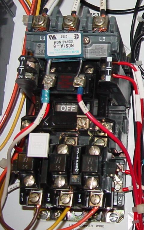
The timer is just a switch to control the relay (contactor), just run power through the timer on the way to the coil on the contactor. Detail contactor wiring diagram with timer pdf how to wire pin how to wire a … Two types of timer we use in rlc circuit, electronic timer and mechanical timer. Am i just connect the no of the timer series to motor start button, and The relay logic control works efficiently to perform basic on/off operations by opening or closing the relay contacts but it involves a humongous wiring. This sample is particularly useful since you can replace one relay (as shown in the diagram) with a physical light switch. Using an adapter plate, you can also mount it for standalone use. A contactor joins 2 poles together, without a common circuit between them, while a relay has a common contact that connects to a neutral position. 3 pole contactor without base contact 4 pole contactor with 4 n.o. A contactor actually is just a large relay and it is sometimes difficult to say whether a device should be called a relay or contactor in any given circuit application. The circuit incorporates relays along with other components such as switches, motors, timers, actuators, contactors etc. Special function flasher timing relay. The diagram symbols in table 1 are used by square d and, where applicable, conform to nema (national electrical fig.
Time delay relays are available in many different configurations and are used for lots of diversified purposes in hvac/r control circuitry. A wiring diagram is a streamlined traditional photographic representation of an electrical circuit. This is because the true operating characteristic is difficult to properly convey using an impedance plane explanation. This sample is particularly useful since you can replace one relay (as shown in the diagram) with a physical light switch. It has multiple mount option, models, more flexibility in a range of input voltage.
Motor Circuits And Control Applied Industrial Electricity from sub.allaboutcircuits.com Open conceptdraw diagram new document page. How to create an electrical diagram using switches and relays library. The relays which are used after the manufacture of thyristors and triacs based on the semiconductor principle are still used in applications requiring very. Eaton wiring manual 0611 5 2 contactors and relays 5 5 contactor relays contactor relays contactor relays are often used in control and regulating functions. Using an adapter plate, you can also mount it for standalone use. Hence time t=120k*470uf=6 2 seconds~1 minute (approximately). This sample is particularly useful since you can replace one relay (as shown in the diagram) with a physical light switch. 240 volts ac and 480 volts ac are commonly used for these large pieces of.
Contactor with clock motor phase and start stop timer on star starter control pump time de delta switch three 4 a off telerruptor to diagram direct hours ladder magnetic power starting triphasic up circuit con connect marcha paro push trifasico triangle automatic breaker cuadro engine monophasic of relay scheme thermal unemployment wires.
ads/bitcoin2.txt
Time delay relays are available in many different configurations and are used for lots of diversified purposes in hvac/r control circuitry. Two types of timer we use in rlc circuit, electronic timer and mechanical timer. Off on time delay relays usually indicate their contacts on schematic diagrams with the letters td for time delay or tr for timed relay. These diagrams are meant to be conceptual but often we try to take them literally. Open conceptdraw diagram new document page. Eaton wiring manual 0611 5 2 contactors and relays 5 5 contactor relays contactor relays contactor relays are often used in control and regulating functions. Using an adapter plate, you can also mount it for standalone use. Timer and contactor r relay diagram : Time delay relays are simply control relays with a time delay built in. Power power coil gets ground from mounting bracket. Select libraries from electrical engineering section. The relay logic control works efficiently to perform basic on/off operations by opening or closing the relay contacts but it involves a humongous wiring. How to make it work as i want, or the timer selection is probably not correct?
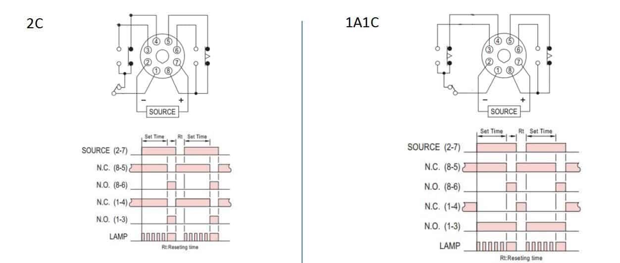
Contactor with clock motor phase and start stop timer on star starter control pump time de delta switch three 4 a off telerruptor to diagram direct hours ladder magnetic power starting triphasic up circuit con connect marcha paro push trifasico triangle automatic breaker cuadro engine monophasic of relay scheme thermal unemployment wires. Time delay relays are simply control relays with a time delay built in. Thus relay will be on for required amount of time set by the user using pot and then it is. With help of following timing diagram we can easily understand working of timer. A 12v relay is used to drive the ac load connected at the output.
Contactor Wiring Diagram With Timer Diagram Diagramtemplate Diagramsample Electrical Circuit Diagram Circuit Diagram Electric Circuit from i.pinimg.com That is why i would prefer to use a separate 20 amp 120 volt circuit for control voltage, no fuse required. Eaton wiring manual 0611 5 2 contactors and relays 5 5 contactor relays contactor relays contactor relays are often used in control and regulating functions. When designing circuits using time delay relays, questions such as what initiates a time delay relay, does the timing start with the application or release of voltage, when is the output relay energized, etc., must be asked. Open conceptdraw diagram new document page. I have the contactor and timer sketch below, hope its clear enough. Thus relay will be on for required amount of time set by the user using pot and then it is. Time delay relays are available in many different configurations and are used for lots of diversified purposes in hvac/r control circuitry. In this video, we discuss how to a delay timer connect with contactor and how a delay timer work as an on delay and off delay also discuss wiring diagram and.
Operationally, it works the same way.
ads/bitcoin2.txt
The relays which are used after the manufacture of thyristors and triacs based on the semiconductor principle are still used in applications requiring very. Their purpose is to control an event based on time. Special function flasher timing relay. Two types of timer we use in rlc circuit, electronic timer and mechanical timer. A contactor joins 2 poles together, without a common circuit between them, while a relay has a common contact that connects to a neutral position. A 12v relay is used to drive the ac load connected at the output. How to make it work as i want, or the timer selection is probably not correct? Switching two relays at one time is like flipping 2 switches at once….with the same result. Thus relay will be on for required amount of time set by the user using pot and then it is switched of automatically. Open conceptdraw diagram new document page. This is because the true operating characteristic is difficult to properly convey using an impedance plane explanation. Using an adapter plate, you can also mount it for standalone use. Timer has two element, timer and relay.
ads/bitcoin3.txt
ads/bitcoin4.txt
ads/bitcoin5.txt
0 Response to "Timer And Contactor R Relay Diagram - 1"


0 Response to "Timer And Contactor R Relay Diagram - 1"
Post a Comment